Tuesday, May 30, 2017

Small Pneumatic Vice Design

I've recently changed my occupation from Engineer to Entrepreneur, yet what that means in my case is, I just have to do more quick engineering work, while balancing some other obligations, and often not have my work be checked by an outside set of eyes. Nonetheless, I love solving all the new problems by dream job has been giving me since day one, and today is no different. My business is starting off as a machine shop, which for those who don't know what that is, is basically a facility that makes often metal parts which are precision cut using industrial machinery from an original larger piece.

The issue we have been having currently, is the time it takes for the industrial machine to cut metal, and the "loading time" which is the amount of time allotted for in this case, a human being (CNC operator) to manually remove the finished part from the operation and load a new blank piece for the machine to start cutting the next consecutive batch.


The bottleneck comes down to physical constraints of our current system set up. We use a dual holding Kurt Vice, which is a very good vice as it provides over a ton of clamping pressure and can hold two pieces at a time. But in terms of practice in this day and age of ever higher competition... innovation is not only key, it is the only way to survive in this type of cut-throat business.


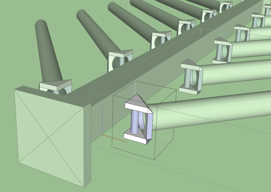
To increase productivity we were thinking of implementing a "Tombstone" which is a steel square prism which can rotate at precise angles and be held firmly. The advantage of using a tombstone in a 4th axis array is that you can load not only 4 tables with a very quick change between table, but you can also machine additional sides of the pieces that are tangential to the rotation of the tombstone thus reducing loading time significantly per part, and optimizing finished product within one running cycle. 

The issue is, we need a universal set up clamps that can be easily switched out for a multitude of parts. Ideally we would like to continue using the standard vice Jaw set up we currently use, however probably a single Kurt nice could be used per table of the tombstone, and loading as many parts is key to success in this business. Therefore, I wanted to see if there was a way to have small clamps which can hold parts very firmly, yet possible be released quickly to lower the loading time of removing finished parts and loading new material.

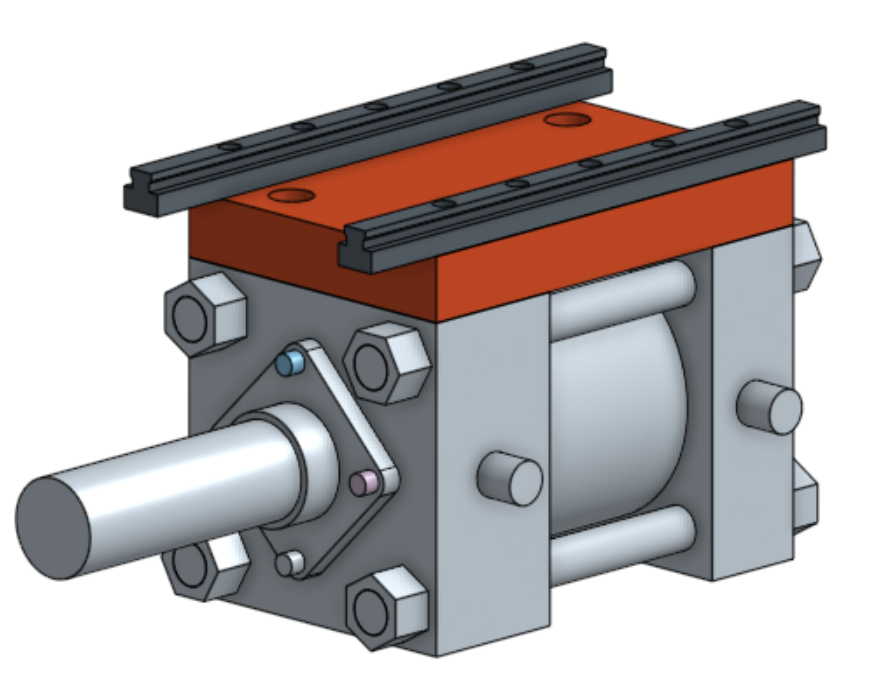
I was considering using a pneumatic air cylinder which in essence is a 2 way piston which can thrust a rod forward or backwards in an airtight cylinder by redirecting air pressure.


The way the pneumatic piston works is by allowing air pressure to fill compartments on opposite ends of a sealed piston rod. 


So I chose to model a relatively cheap pneumatic cylinder which has a large diameter bore to provide a lot of force with a small stroke length, since the jaws in essence don't normally have to open that wide to release the part. The length of the cylinder is also key to keep the vice compact, and able to fit neatly onto a tombstone array. I was also interested in a cylinder with pretty thick squared off stock, so that they can be machined and ground flat to ensure proper precision can still be held true.
An adapter plate can then be bolted on top of the cylinder which would then allow the bolting of a precision linear rail. 


Saturday, April 15, 2017

Flat Crochet Mathematics

A friend of mine approached me with a very interesting problem where the intersection of many disciplines can come into play which would make way for an interesting exercise. She was knitting flat pieces of crochet, and noticed the fractal patterns that appear, and from the number of crochet examples she had in hand, she was experimenting with various techniques to see how the overall pattern would emerge. I myself didn't know much about knitting, but the mathematical aspects of the problem were very intriguing. There must be a method of breaking down the knitting process into a formula or set program, where a simple change of parameters can provide dramatic changes in the overall pattern.

After a brief google search I learned of certain terms used in the actual physical knitting of crochet, the chain, the simple crochet, and the slip stitch. The act of knitting these flat masterpieces of tapestry also always seem to emanate from the center. An interesting method of trying to define a simple algorithm of a pattern I thought could be used with cylindrical coordinates.


The cross can represent a single crochet, the oval a chain, and the dot a slip stitch


If the center of the tapestry can be considered the origin, then the generation of the pattern can emerge with the simple variables of angle, length from the origin, and the sequence of crotchet knots at the specified point on the flat plane.


A pattern can then be made by adding additional rules to each of the parameters, such as a formula which controls the radial length "L" to allow gaps based on it's position of angle, and how many concentric circles have already been made up to that point. The sequence of crochet parameters can also be connected to the formula of L and theta, to create patterns that are unique to create radial arms, of rows of concentric rings.

Once a set program could be made to show simulated results based on user input of those specific parameters, then one could see how the resulting patterns can emerge from scale and complexity.


Specific formulas for theta can be the following

2pi/No radial arms


The mathematical looping can be flattened by dividing up the 3D curves into individual curves that start at the very bottom to the very top.

Applying a Hessian to the parameterized curve can identify individual curves either sloping up or sloping down which can be quickly represented using simple 2D vectors.

Tuesday, January 27, 2015

Buffalo Algal Turf Scrubber Project


The job consisted of designing a tertiary treatment plant which could treat the nearby buffalo surface water from the local river system. I was tasked as the primary design engineer for the project and designed the series of constructed modular system and budgeted most of the construction costs of the project.

The apparatus is basically a long channel which allows autotrophic growth on its surface and cleans the incoming water stream by the time it leaves the first loop of treatment.


Each channel was designed to be highly cost effective and functional. The overall material chosen would provide a high level of protection from the elements as well as from the incoming fluid stream.
Bi section slice of a typical stretch of channel

Steel rebar (silver), would be coated in primer (brown) and finally in an epoxy sealant (yellow)
The wooden channel would sealed in several coats of epoxy sealant and covered with a 8 mm thick geotextile mat to prevent leakage across the channel.
Each section of channel would interlock and be held in place through these intermediate 
Flow Rate Calculations

$ V = \frac{ k } { n }  R_h ^\frac{2}{3} S^\frac{1}{2}  $

$V = \frac{ 1.4859 ft^\frac{1}{3} } { .02 s } * ( \frac{ W h } { W + 2h } )^\frac{2}{3} (0.015)^\frac{1}{2} $

If W = 16" h = 1.5 "

$ V = 2.029 \frac{ft}{s} $

$Q = V * A = .338 \frac{ft^3}{s} $

$Q = \frac{ 0.338 ft^3 }{s} \frac{7.48052 Gal}{1 ft^3} \frac{60 s}{min} = 151.75 \frac{gal}{min} $


Dump Bucket Moving Centroid Calculations

Biomimicry Floor Joist Concept Consultation


The consult for this research consisted of developing new ways to design floor joists which would allow some level of horizontal deflection to provide some level of structural stability during the event of an earthquake. I was inspired by the structure of a feather which consists of a hierarchy of interconnected beams which hold their shape firmly, even in the extreme forces experienced during the turbulent conditions of flight.

Illustration of the micro structure of a feather
Initial brainstormed methods of interconnected steel structures which allowed lateral and bending moments while maintaining rigidity


Monday, January 26, 2015

Solar Array Consulting Project


An architect consulting company which specializes in utilizing biomimicry design to overcome construction challenges. Biomimicry is the use of studying nature, in order to adapt the forms to help aid an engineered solution. The design challenge posed to this client was to design a solar array which can extend the surface area of a roof while maintaining an aesthetic appeal. The muse to this problem in my instance was the leaf, which is held in place from a stem or branch and broadens the field of surface absorption of sunlight despite being tethered to the central location of its central trunk or stem. The leaf also has the ability to maneuver and tilt to maintain an optimal angle towards the sun through minimal movement from the central base location.
Brainstorming ways to hold the long blade portion of the solar panel upright yet allow actuated movement.


The shape of the solar panel allowed for beautiful intricate patterns which can extend past the reach of the roof structure, while providing a sense of canopy and natural beauty from the familiar design.


I had designed the solar array actuated joist system in Autodesk inventor to analyze the limits of design loads to have the ability to hold the light polyurethane solar panel firmly even in the event of wind and snow. 


Small Restaurant Design


While working at a local architecture design firm in New York City Staten Island, I was tasked with designing a small restaurant for a local investor couple client. I would be in charge of most of the design work in terms of infrastructure as well as interior design work. This was a chance to utilize my creativity from my artistic background as well as my attention to detail from my engineering studies, to ensure this small striving group of hopeful entrepreneurs get the best bang for their buck when they placed all their hopes and dreams into my able hands. 
This was a picture of the outside of the original site which was a local deli which sold a variety of groceries and other amenities.
The first plan of action was to take an overall survey of the site since the previous owner and the city did not have accurate blueprints of the site. 
Blueprint of original site layout 
Layout starting to be divided into specific sections with adequate electrical and water supply lines placed according to code


Once the clients had approved of the last series of preliminary designs and graphic renderings, they had invited me to come visit periodically to check up on their progress. After the budget reports were finally settled, I took a few pictures of the subsequent construction once the final design features were approved and reviewed.