The Renaissance Man
"A man can do all things if he will."
Embodying a basic tenet of Renaissance humanism that humans are limitless in their capacity for development, the concept led to the notion that people should embrace all knowledge and develop their capacities as fully as possible.
While working at a local architecture design firm in New York City Staten Island, I was tasked with designing a small restaurant for a local investor couple client. I would be in charge of most of the design work in terms of infrastructure as well as interior design work. This was a chance to utilize my creativity from my artistic background as well as my attention to detail from my engineering studies, to ensure this small striving group of hopeful entrepreneurs get the best bang for their buck when they placed all their hopes and dreams into my able hands.
This was a picture of the outside of the original site which was a local deli which sold a variety of groceries and other amenities.
The first plan of action was to take an overall survey of the site since the previous owner and the city did not have accurate blueprints of the site.
Blueprint of original site layout
Layout starting to be divided into specific sections with adequate electrical and water supply lines placed according to code
Once the clients had approved of the last series of preliminary designs and graphic renderings, they had invited me to come visit periodically to check up on their progress. After the budget reports were finally settled, I took a few pictures of the subsequent construction once the final design features were approved and reviewed.
I had a very specific vision of how I wanted to draw the cover to my novel in progress. The idea I had for the front cover to my novel involved a picture of a dove as the central focus. I wanted the dove to be very detailed and highly accurate. I imagined the dove to be anatomically correct, to the point where I wished to draw the entire dove from the inside out. I planned on super imposing entire body systems over each other, to ensure a completely accurate image of the full exterior for the front cover. As you open the book, you would periodically see the other bodily systems underneath layer by layer and all accurate from the front and back view as well.
The front cover artwork would represent the overall theme of the novel which shows a symbol of peace tainted in human blood. The background would show the remnants of a world deeply scarred and eaten away from human civilization with much of its resources depleted and waning. The overall image from a distance would look similar to that of a bible, with the help of large very tall space elevator towers specifically placed around the earth's profile. From a distance the overall illustration would form a cross centered around a glowing halo of the Earth's mantel, and the image of the holy spirit at the heart of the overall artistic piece. This gives allusion to the religious references through out the book, from Christian faith and religious practices.
The overall idea came to me in a dream, and I had no paper or pen on me at the time, so I made a rough sketch using Google draw before the image left me.
Rough sketch of overall idea. A large dove in the middle surrounded by a the earth sliced through the center with large buildings and debris covering the surface and mantle.
Once I had some paper I decided to sketch out the dove more clearly and began to get a more clear picture of how it would turn out.
Early Sketch of the dove
Dove Bird Wing Study
I was considering drawing a dove looking down, wings open, about the take flight with plumage fanned out. Face and feathers and breast blood stained. The features themselves, would be influenced by mathematical design with specific number values such as Fibonacci's sequence and geometric proportions such as the golden ratio.
The outer dimensions of the book should be in the same golden ratio as well as many of the ratios of features such as the eye elliptic ratio, and length of width of other features to make the overall piece very pleasing to the viewer.
To do this overall artwork piece, would take some methodical planning and careful execution, so I split up the tasks based on biology. I decided to draw the dove from the inside out, starting with the foundation of the skeletal system in which the orientation would be dictated by the final rendered image of the exterior outline so I decided to start there at first.
Once I had a rough idea on how the exterior would look, I dove in and started finding high detail images of the skeletal system and overlaid various images over each other to draw both the front and back at the same time.
I decided to separate each component into layers as I drew, so if any changes needed to be done, I could easily alter just one body part at a time.
I started to draw out the outlines in Auto CAD because I enjoy the ability to organize and be meticulous to detail.
Final sketch of dove skull from the front view
Final Outline drawing of the skull back view
I then imported the Auto CAD outline into Photoshop and started doing some shading
Final shaded image of the dove skull from the front view
Shaded Image as seen from behind of the Dove Skull
I came up with my own technique, on how to utilize the Auto CAD sketches and Photoshop effectively to create accurate depictions of each piece.
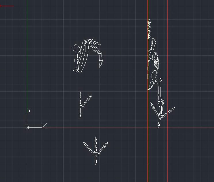
Image of the the Auto CAD rendered image of the overall skeletal System
On top of the overall blueprint, I import the individual drawn pieces and place them over the outline.
A friend contacted me for help in sizing a pump for a drip irrigation system for an exterior garden cultivation project. The idea was to store water in Rain Barrels to provide some head elevation, and use a pump to provide the additional head needed to adequately sprinkle the water to the specific portions throughout garden.
My friend provided me an aerial view of the planned construction of the distribution system along with some references to the diameter of pipes he was expecting to use.
One of the first things I would need to accurately size everything, is first knowing the final drip rate expected at the end. If an expected amount is really needed a recommended value could be 1/4 inch of water per day found through this Link.
The first thing I was going to do was calculate the major head losses across the system
Calculating the major head loss across the system, can be found using the formula below
$H_L = F * (L/D) * \frac{V^2}{2g}$
Where
F: Friction factor due to roughness on the interior of the pipe
L: Length of pipe
D: Diameter of pipe
V: Average liquid velocity within the pipe
g: Acceleration of gravity
Looking off the provided reference guide, I made a table to start calculating the major head losses across all the reported stretches of pipe.
Color Ref.
Pipe Length [ft]
Diameter [inch]
Major Head Loss
Red
15
1
1.40625E-05
Red
18
1
0.000016875
Red
50
1
0.000046875
Red
90
1
0.000084375
Red
50
1
0.000046875
Blue
12
.75
0.000015
Blue
15
.75
0.00001875
Blue
4
.75
0.000005
Some of the missing information I need to accurately finish the rest of the calculations is knowing the vertical information of the case study. In particular, the height of the water surface from the rain barrels to the point where the water exits the system and onto the plants.
Here are some of the situations of interest that may arise from these instances
I would want to know if the final exit height will be higher than the water surface, like if the rain barrels were located on a low elevation relative to the final destination of the plants.
If the final drip line height is lower than the rain barrel surface water level height (This would result in needing a small pump if at all needed)
Does the water have to be ejected from the opening out a certain distance to the plants?
To be continued until I hear back with the necessary information to post the final values.
The.barrels are.on.cinder blocks so the water would flow.downwards from an elbow fitting.to.the.inlet of the pump. Approximate drop 6 inches
Then from the tees on the mainline a fitting.for poly-pipe would be attached then from.that line I would poke holes.for 1/4 inch transfer barbs and attach 1/4 inch drip.line to that.
$ \frac{ P_1}{ \rho g } + \frac{ ( V_1 )^2 } {2 g } + Z_1 - H_L + H_P = \frac{ P_2 } { \rho g } \frac{ (V_2)^2 }{ 2 g } + Z_2 $
This is was originally a linear actuator that moved some oceanic sensor equipment from side to side, I've removed both support rods from the linear bearing housing and put them both to the side
Here is a look at how rusted the support rails are, they are in dire need of sanding and polishing to function properly
These are the Thomson linear bearings held by a custom machined aluminum housing
I decided to draw each of these salvaged items in AutoCAD Inventor as parts and experiment with assembling them in different configurations later on for analysis
Y-Axis: Acme Screw
Here are some general dimension of the Y-Axis Acme Screw [inches]
This is the linear Bearing Housing
Looking at it a bit closer, there was a measured screw pitch of 20 thread per inch
One of the parameters of interest would be the maximum allowable bending moment of the aluminum pipe through a radial force on the pipe supported on two ends.
Axial bending load geometry parameter set up across Pipe
Cross Section of Pipe showing two areas of integration against stress distribution
$ M = 4 \sigma_y \frac{E}{\sigma_y R} \int_ 0 ^ \frac{ \sigma_y R }{E} \!
The job consisted of designing an apparatus that would hold firmly a set of pipes to allow precise cnc machining of several holes at specific locations along it length. The apparatus would fit inside the tooling dimensions of a HAAS VF2 Vertical CNC Milling Machine.
Picture taken of HAAS CNC machine from the manufacturing client
Utilizing the maximum working dimensions of the machine along with the known dual compressed air ports available on the working platform of the machine, I began to brainstorm. My first series of ideas would be aimed towards sketching some mechanical means to hold the series of pipes in place.
I came up with the idea of utilizing a type of clamp with can come over the sides of the pipe and hold down it down through some type of vertical linear motion. I came up with a rough idea a type of lever arm with arbitrary parameters to be used to calculate lengths later on.
Here the lever arm has a pivot point to the left end of of length "L" and the free end is located at (Xr,Yr) from the pivot point as the origin. With the lower point of the lever arm held at a horizontal stature to the vertical datum, the angle $\theta$
Here the vertical actuator has moved downwards from the datum point lengthening the lower portion of the arm by a distance $ \Delta L $
$ X = R \cos( \arctan( \frac{ \Delta Z } {L} + \theta) $
$ Y = R \sin( \arctan( \frac{ \Delta Z } {L} +\theta ) $
The lever arm dimensions should have a proper radial length to properly reach the top of the pipe when the linear actuator reaches the "Zmin" below the datum, and have a reasonable clearance from the upstroke when the linear actuator reaches "Zmax" from the horizontal datum.
Here is a working virtual prototype of how the clamp would work while connected to a dual hydraulic actuator.
After a cost analysis of the clamp idea, it quickly became apparent that custom manufacturing of such tight tolerance parts of working clamps over time would be very costly. My next series in my brainstorming path would take on the form of vertical clamps.
My first conquest was to design a platform which would be bolted on top of the existing milling table fixture. The platform would be milled completely flat and the series of holes would provide a variety of components to be bolted on, yet allow some flexibility to further any redesigns if necessary.
3D Assembly of Platform case study
View of a 3D rendered view of the platform from the case study.
Here is a picture of the final machined platform fresh from the machine shop.
The platform would then be installed onto the working fixture in the HAAS machine with the help of a forklift.
Platform attached to working fixture of the CNC machine bed with clamped down pipes on the right