Friday, October 3, 2014

Fixing Casement Window

I decided today to try and fix the casement window which is suppose to open a window through a means of cranking a handle. The problem is the actual assembly was missing and the only thing present was the rail on the side of the window.

A casement window is opened through a mechanism where a rigid arm pushes on the window through often some sort of wheel and track system through the rotating force of a lever and gears.


The generic window crank assembly wouldn't have been a quick install since the problem arose in the incompatibility of the wheel on the tip of the arm, and the rail system on the side of the window.
This is the wheel on the tip of the arm that pushed on the window
This is the rail that was original to the window, notice that it has a groove to accommodate a wheel with a very specific cut notch so that the wheel slides snugly and cant slip off the track when sliding across


The window was a bit old and the parts would have to ordered from the manufacturer if they were even in business any more. Nonetheless this would frustrate the typical homeowner, but this just brought me a rush of joy for a chance to solve a new problem.

There were essentially two ways to solve the problem, either you modify the wheel on the generic assembly, or you can make a custom rail to fit around the generic replacement found at your local hardware store.

This is a quick sketch of the two possible solutions. Either modify the wheel, or make a custom rail


I decided to choose the latter because removing that wheel and carving that notch via lathe on that plastic wheel wouldn't have been such a big deal. Even if I had to tap the metal housing to screw in the wheel again it still would have been less work than the rail. I chose to do the rail because, moving that window through simple friction involves a lot of force and friction, and I wasn't really at all confident as to the strength of that plastic wheel. The plastic wheel felt flimsy and I think it would have easily cracked and not withstand the loads once I removed that material and changed its shape.

I got a square block piece of aluminum stock and made sure that the inner square hole length was slightly large than the diameter of the plastic wheel.

I then measured the diameter of the shaft part of the wheel

This measurement would be essential to making the  sliding rail width that the wheel would slide on
Using that measurement I marked off where the rail would be cut on the aluminum square block

Then came another engineering hurdle that I had to overcome, the issue of cutting the rail with only a jig saw, drill, and drill press at hand with simple tools. It was a tricky cut because I had to cut through one side of the square side but not the other.

My first attempt was to see if I could jerry rig something to make the jigsaw work because if I could make it work, it would save me time, and it would be much easier to make a smooth linear cut.

To solve this problem involved some sense of engineering and 2D thinking which I very much enjoyed. I drew out some of the problem solving instances I would need to think about prior to solving the problem and just made up some arbitrary parameters to define the problem.

The way the jigsaw works is, it plunges a blade up and down in a linear fashion through a specific length of stroke. I had to investigate to see if that length of stroke was within clearance distance to cut one side of the aluminum block and not the other.

This is a quick sketch of the jig saw when looking at it head on (cutting blades facing you). I made up some arbitrary lengths that are of importance in this problem. Lo is the length when the jig saw is making the highest stroke into itself or the shortest length the blade relative to the supporting platform.  "S" is the length of the stroke or the largest difference in length the blade makes when cutting. "delta" is some arbitrary length which is a factor of safety buffer distance we can risk later during practice. 
This is the same situation now split into the two extremes of the stroke to better show what these arbitrary distances I came up with actually means. "C" is the overall clearance distance which includes the triangular point of the blade which is very important because it could still plunge into the metal and damage either the aluminum side or the blade itself. 


There are two possible scenarios that could result from this situation, one being beneficial to me, and the other forcing me to find another method. The first situation is that there exists a length that I could hold the jigsaw above the rectangular stock so that the clearance "C" is less than the inner side length "L" and therefore a single cut could be possible.

The first beneficial scenario where the blade clearance length "C" is less than the length of the square block stock making possible a single cut through the stock block.
This is the second scenario where "C" is larger than "L" therefore cutting only one side of the aluminum stock block would not be possible and therefore we would be forced to find another way to cut the aluminum.


After doing some measurements and a little bit of math, and some failed attempts just to make sure the math was right.. It was the second scenario so I was forced to find another way to make the cut.

Since it was already pretty late to try and rent out some tools or bother someone to finish the job, I had to resort to using the other tool I had at my disposal the drill press. The right tool would have been a dremel, or maybe a large aluminum bandsaw with some kind of jig, or maybe a cutting table with a fine metal cutting blade retrofit.

But alas I press on and start to find some drill bits which are slightly smaller than the overall width of the gap.


I started to drill holes as close to each other as I could with my cheap drill press and stay within the lines because I knew you could always remove material but can't add on.

The larger the diameter of the drill, the less I would have to grind down on the sides, but then the holes would have to be dead center all the way down and not have a lot of room for error.
One of the benefits of having a X-Y vice is for these instances where you'd like to drill a series of holes all in a row. 
Therefore to make the next series of holes, you would simply crank the handle and drill.
Before I knew it, I had a series of holes all cut within that small window tolerance of the width of the desired slot size
If you have the holes close enough together, you could easily break the aluminum between the holes with a simple set of needle nose pliers by just bending back until it breaks using the frame as the lever pivot point.
Making some quick work of this brute force slot cut through some crude methods.

This is how the bar looked like after the use of the pliers, no other refinement could be done without some kind of mechanism  to make the parallel cuts.


I decided to call it a night, and the following morning I managed to borrow a angle grinder to do some quick work of the rough edges of the drilled holes.

I clamped the angle grinder down and made sure it was secured in place

I started to grind down the rough edges little by little getting closer to the marked edge to where it needed to be
I also periodically sanded down the inside with a square file to ensure the smooth finish inside and out
To get closer to where the actual edge needs to be, I decided to file the edges to a smooth finish
I inserted a metal bar on the floor of the aluminum car stock so I could file the sides away without scraping the floor of the aluminum  block.
Finally got the groove smooth enough to have the mechanism slide effortlessly
The final step involved drilling a few holes

Thursday, August 21, 2014

Fixing Center Console storage in the car


A small little plastic piece had broken off in one of the interior of my vehicles. The absence of this small little piece resulted in an annoying occurrence that the lid which covers the center console was permanently open and could never close. (Please see video below to clear up any confusion).


After inspecting the part in detail, it was really clear and obvious what the problem was, but how to solve it was a different story. I understand the original design and how it would work and why it doesn't now. I made a sketch to show what I understood of the mechanics of this small locking mechanism of how the original engineers intended.

At the end of the door hinge is a latch (shown in red) which slides and locks in place through a rectangular sliding piece (shown in grey). The shape of the latch is convenient to easily slide the rectangular hole catch just by closing the lid. The spring loaded button on the side could then be use to free the latch and open the console.

The present situation is that the plastic latch piece was broken and has lost its trapezoidal shape to catch on the rectangular hole lip. I drew out a cross section of the previous and present situation down below.


The previous scenario show on the left where the latch mechanism was working smoothly. The presently broken situation is shown on the right with an outline of the missing piece that had broken off. Notice how the present shape does not allow the latch to catch on anything and is therefore the reason why the door merely slides the button across but does not lock in place.

 
Here is a close up of the underside of the door cover and the latch mechanism


After cutting a small piece of wood, I drilled out a lollipop shape to accustom a rubber stopper mechanism under the plastic cover              (See next picture for clarification)

I wanted the wood to lay flat against the underside of the plastic cover however there was this rubber end stop in the way. The lollipop milled hole helped work around that problem so the wood could lay flat.
After I had the small piece of wood flat against the underside of the plastic cover, I bent a sturdy nail using a vice at a 90 degree angle and drilled a hole through the U-shaped slot and hammered the nail through.

This is a close up of the progress so far. The wood lays flat against the plastic and I drove the bent nail through a drill hole I made previously using a drill press and the solution is coming together smoothly.

There is a problem though that due to the wood, the plastic cover does not lay flat anymore against the underside of the padded cover :(
To solve this problem, I decided to cut through the plastic cover which holds the padded foam cushion. I would try and mark off the size of the rectangular wooden piece and get to work.

Using the drill press I made a series of holes outlining the dimensions of the rectangular wooden piece.

With a simple heavy duty flat head screw driver or a chisel you can hammer out the plastic between holes and remove the plastic rectangular chunk.

This is the rectangular plastic piece removed via a crude drill and hammer method

Now you can see that the plastic cover lays down flat and will not warp or stick out with the wooden insert underneath on the corner.


Now you can screw the padded cover to the spring loaded piano hinge before placing the plastic cover back on.

With the bent nail in place the latch would work as long as you hold the button down and let go when the lid is shut. To return full functionality which would include the passive shut and lock ability, I would need to weld a smooth rectangular piece to the nail to slide the rectangular latch back and over the catch.

This is an outline of a welded metal piece that would work perfectly and return full functionality as the original 

Wednesday, April 9, 2014

Resurrection of the Collapsed Gazebo


Gazebo Roof Collapse

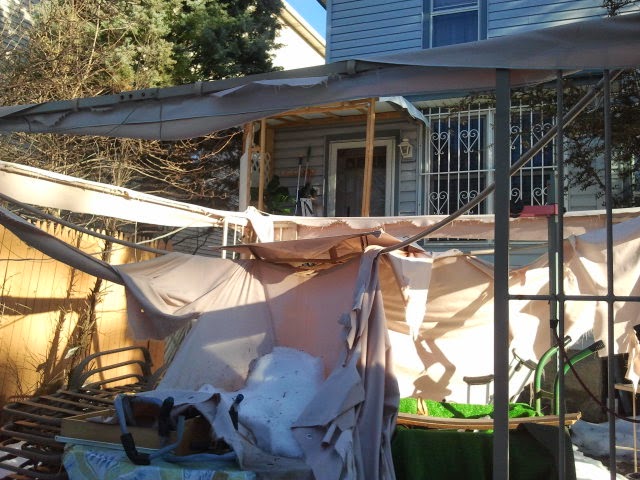
Snow had accumulated a great deal on the roof canopy of my gazebo in the backyard over the winter, the roof buckled from the excessive load, and the new bowl shaped roof proved useful in collecting even more snow as the winter progressed. The excess snow loading finally got heavy enough to pierce through the tarp by winter's end. Instead of tossing out the entire gazebo, I thought I'd use this occurrence as an opportunity to practice some long forgotten skills from back in my first years of college and use them to resurrect the Gazebo after it's bitter fight with the harsh winter. There was no real hurry to fix the roof really, since everything underneath it could have survive the winter uncovered from the elements with no problem. Instead, my mindset was set on the fact that this could be a great opportunity to flex some real mental muscle before doing some manual labor when the weather gets nicer.
This was how I saw the Gazebo the first day I notice the roof collapse. Luckily there was nothing fragile underneath being stored over the winter.


The Game Plan

I thought I'd rebuild the roof using a Gable Roof Truss Configuration and try and maximize my material use through tapping into the valuable resource of mathematics and engineering.

This is a CAD drawing I made of the roof truss design I was thinking of using. It might be over engineered, but at least this time I'll be certain the roof wouldn't collapse again under another snowy winter for years to come (now that a real engineer did their homework)

Since it was still winter, I decided to make use of my time indoors by doing one of my favorite past times and become lost in a world of mathematics and calculate what would be the optimal lengths and placements of each truss to make use of the standardized length pieces of lumber available at my local hardware supply store. I was considering calculating the optimal lengths and marking them on the 2×4 pieces prior to cutting them. 

Here is a series of pictures for the overall end goal idea and planning for the roof truss:

The red lines represent all the final cuts I would make on the pieces of lumber.

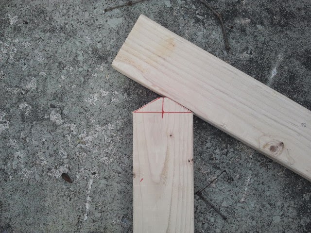
The orange lines represent the lines I would draw on the pieces of lumber themselves with a Tri Square, to help make sure everything is lined up perfect.

Lumber Lengths


Ref No. Length Formula
A $ A =\frac{ W }{sin(\theta)}$
B $B =\frac{W}{Tan(\theta)}$


XXX


Roof Geometry Mathematics

So remember, this amount of planning and calculating is not at all necessary if one were to build a small roof for a small structure. If building this small roof right away was a pressing matter, I'd probably would've just gone out that same day and bought about a $100 worth of lumber and deck screws and piece this whole thing together in about a day. For safety I probably would have looked at some engineered trusses and follow their design measurements or follow an ASCE standard for roofs, or the FEMA Snow Roof load guide. But nonetheless, I didn't really feel like working in the freezing weather, so doing all this math indoors was just a fun project for me to do over a weekend, and a way to keep my mind sharp during the dull winter.

So first things first, picking out the design constraints...

I was thinking of using just one type of lumber to make my life easier and to make the math just all algebra and keep it universal for anyone else who wished to maybe use the equations for their own specific lengths. I gave the parameters to the dimensions of the wood "L" for "length", "W" for "width", and "T" for thickness. Below is a picture to clarify any confusion:


The plan area of the Gazebo was 10 feet by 10 feet so I figured I could get away with using 2×4×10's using the entire length of a piece of wood for all the bottom pieces. So the bottom pieces would only need some slanted cuts at the very ends as seen in the picture below:

Truss Design Showing the mid-lines of all the truss pieces in dotted yellow, center-line in green, and emphasizing the bottom length "L" piece
Note: For the rest of the calculations I'll only show pictures of the work from one side, due to the symmetry of the problem. 


I was thinking that the only variable I'd like to have should be the angle to the slope of the roof which would later dictate the rest of the truss lengths and geometry. The final goal would be to have all the lengths described full in terms of the lumber product dimensions of "L", "W", and "T" and with one one variable of "θ".

I'll do one simple example so you could see what I'm talking about.

Zooming in real close to the bottom left corner:


$ A =\frac{ W } {sin(\theta)}      ,         B =\frac{W}{Tan(\theta)}$


$ C = \frac{L}{2} - ( \frac{W}{2} + \overbrace{ \frac {W}{Tan(\theta)} }^{B})$


$ D = \frac{ C }{ Cos(\theta) } = \frac{(L-W) Sin(\theta) - W Cos(\theta) }{2 Sin(\theta) Cos(\theta)} $

Next I would want a good place to put the vertical beam between the corner and the main middle column. I'd like to place it in the exact center between structural load points so I'll first calculate the length "G" and place the middle of the vertical column underneath it.

The right end of G is a bit complicated to get that exact measurement so I'll zoom in on the right end so we could get an opportunity to do some more math for a more precise measurement.


$ F = W Tan(\theta) $,    $ E = \frac{ W/2 }{Sin(\frac{\pi}{2}-\theta})} $

 $ if ( \frac{\pi}{2}-\theta ) = \psi $

$ E = \frac{ W/2 }{Sin(\psi)} $

So again looking at the big picture of calculating the length "G" involving most of the created parameters we calculated so far:

$ G = \frac{A}{2} + D + E + \frac{F}{2} $
$\therefore$
$ G = \frac{ (L-W) Sin(\psi) + W[ Sin( \theta)Sin(\psi) + Cos(\theta)] } { 2 Cos(\theta) Sin(\psi) } $

So basically all that effort in algebra and regrouping to find the length "G" was really just to find out the optimal place to put that vertical truss that supports the midpoint of the hypotenuse of that large triangle. So we divide "G" in half and we put the vertical truss so it lines up directly underneath it's mid-line.

To calculate one of the heights of the vertical truss well zoom in for clarification


Zoomed in on the area where the vertical truss meets the sloped roof support for clarification on length "J"
$ J = \frac{W}{\cos(\theta)} $

Placing the vertical truss back in, we will calculate the length "H" as the length of the leg of the purple right triangle opposite angle θ

 $ Sin(\theta) = \frac{ H } { (G/2) - [(A/2)+(J/2)] } $
$ \therefore $
$ H =  \sin(\theta) *  (  \frac{G}{2} - [\frac{A}{2} + \frac{J}{2} ] ) $

$ H = \frac{\tan(\theta) * ( \sin(\psi) [ L + W (\sin(\theta) - 1)] + W ( \cos(\theta) - 2 \sin(\psi) ) -  2 W \sin(\psi) }{4\sin(\psi)} $

The next calculation will be calculating the other height on the vertical truss which is named "I" shown in cyan blue, using the lengths shown in red and angle theta shown in yellow.
$ I = [\frac{G}{2} - \frac{A}{2} + \frac{J}{2}]\sin(\theta) $

$ I = \frac{ [ (L-W)\sin(\psi) + W ( \sin(\theta) \sin( \psi) + \cos(\theta) ) ] \tan(\theta) - 2W \sin(psi) +2W \tan(\theta) sin(\psi) }{4 \sin(\psi) } $

The next length calculation will be "N" which will later help to calculate length "K"

$ N = \cos(\theta) [ \frac{G}{2} - \frac{A}{2} + \frac{J}{2} ] $


$ K = \sqrt{ ( C - N )^2 + I^2 } $

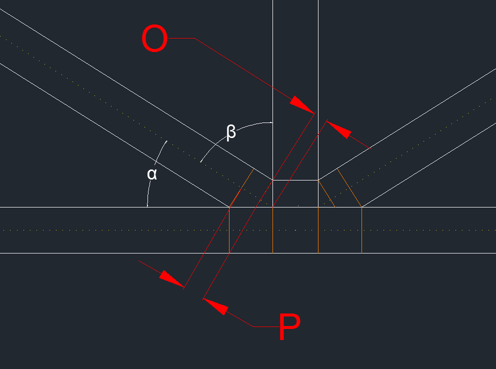
Taking a close look at when the middle truss meets the center of the bottom support beam at its center

$ \alpha = \arcsin( \frac{I}{K}) $

$ \beta = \frac{\pi}{2} - \alpha $

$ O = \frac{W/2}{\tan(\beta)} $

$P =\frac {W/2}{\tan(\theta)}-O $


This is the final Roof Truss Design known as a Gable Truss Design
These are some of the arbitrary labeled dimensions I came up with that would be useful in helping me make sure everything i
Assuming length "L" was 10 ft, the width was 3.5 inches, and a slope of 30 degrees, these are the following calculated values


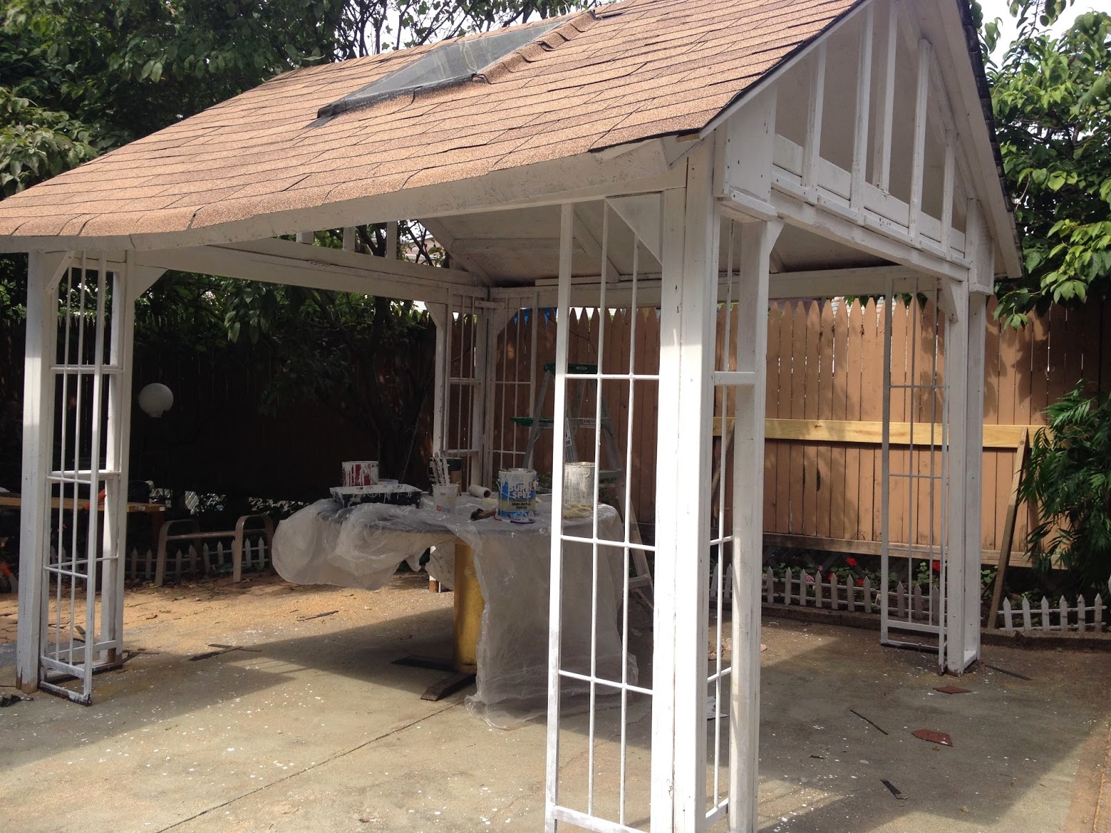
This is the overall idea for the construction of the roof with reinforced wall support