Gazebo Roof Collapse
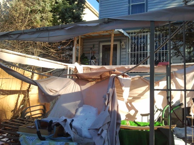
Snow had accumulated a great deal on the roof canopy of my gazebo in the backyard over the winter, the roof buckled from the excessive load, and the new bowl shaped roof proved useful in collecting even more snow as the winter progressed. The excess snow loading finally got heavy enough to pierce through the tarp by winter's end. Instead of tossing out the entire gazebo, I thought I'd use this occurrence as an opportunity to practice some long forgotten skills from back in my first years of college and use them to resurrect the Gazebo after it's bitter fight with the harsh winter. There was no real hurry to fix the roof really, since everything underneath it could have survive the winter uncovered from the elements with no problem. Instead, my mindset was set on the fact that this could be a great opportunity to flex some real mental muscle before doing some manual labor when the weather gets nicer.
 |
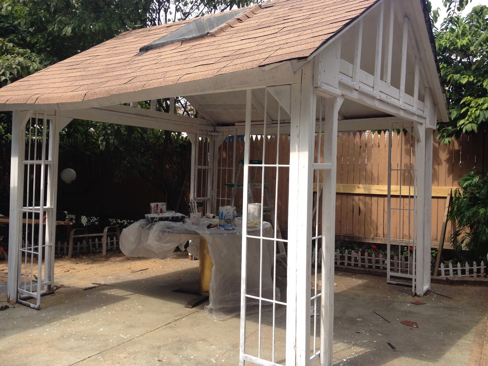
| This was how I saw the Gazebo the first day I notice the roof collapse. Luckily there was nothing fragile underneath being stored over the winter. |


The Game Plan
I thought I'd rebuild the roof using a Gable Roof Truss Configuration and try and maximize my material use through tapping into the valuable resource of mathematics and engineering.

This is a CAD drawing I made of the roof truss design I was thinking of using. It might be over engineered, but at least this time I'll be certain the roof wouldn't collapse again under another snowy winter for years to come (now that a real engineer did their homework)
Since it was still winter, I decided to make use of my time indoors by doing one of my favorite past times and become lost in a world of mathematics and calculate what would be the optimal lengths and placements of each truss to make use of the standardized length pieces of lumber available at my local hardware supply store. I was considering calculating the optimal lengths and marking them on the 2×4 pieces prior to cutting them.
 |
| The red lines represent all the final cuts I would make on the pieces of lumber. |
 |
The orange lines represent the lines I would draw on the pieces of lumber themselves with a Tri Square, to help make sure everything is lined up perfect.
|
| Ref No. | Length Formula |
| A | $ A =\frac{ W }{sin(\theta)}$ |
| B | $B =\frac{W}{Tan(\theta)}$ |
XXX
Roof Geometry Mathematics
So remember, this amount of planning and calculating is not at all necessary if one were to build a small roof for a small structure. If building this small roof right away was a pressing matter, I'd probably would've just gone out that same day and bought about a $100 worth of lumber and deck screws and piece this whole thing together in about a day. For safety I probably would have looked at some engineered trusses and follow their design measurements or follow an ASCE standard for roofs, or the FEMA Snow Roof load guide. But nonetheless, I didn't really feel like working in the freezing weather, so doing all this math indoors was just a fun project for me to do over a weekend, and a way to keep my mind sharp during the dull winter.
So first things first, picking out the design constraints...
I was thinking of using just one type of lumber to make my life easier and to make the math just all algebra and keep it universal for anyone else who wished to maybe use the equations for their own specific lengths. I gave the parameters to the dimensions of the wood "L" for "length", "W" for "width", and "T" for thickness. Below is a picture to clarify any confusion:
I was thinking of using just one type of lumber to make my life easier and to make the math just all algebra and keep it universal for anyone else who wished to maybe use the equations for their own specific lengths. I gave the parameters to the dimensions of the wood "L" for "length", "W" for "width", and "T" for thickness. Below is a picture to clarify any confusion:

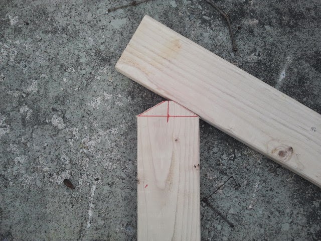
The plan area of the Gazebo was 10 feet by 10 feet so I figured I could get away with using 2×4×10's using the entire length of a piece of wood for all the bottom pieces. So the bottom pieces would only need some slanted cuts at the very ends as seen in the picture below:
 |
| Truss Design Showing the mid-lines of all the truss pieces in dotted yellow, center-line in green, and emphasizing the bottom length "L" piece |

I was thinking that the only variable I'd like to have should be the angle to the slope of the roof which would later dictate the rest of the truss lengths and geometry. The final goal would be to have all the lengths described full in terms of the lumber product dimensions of "L", "W", and "T" and with one one variable of "θ".
I'll do one simple example so you could see what I'm talking about.
Zooming in real close to the bottom left corner:

$ A =\frac{ W } {sin(\theta)} , B =\frac{W}{Tan(\theta)}$

$ C = \frac{L}{2} - ( \frac{W}{2} + \overbrace{ \frac {W}{Tan(\theta)} }^{B})$

$ D = \frac{ C }{ Cos(\theta) } = \frac{(L-W) Sin(\theta) - W Cos(\theta) }{2 Sin(\theta) Cos(\theta)} $
Next I would want a good place to put the vertical beam between the corner and the main middle column. I'd like to place it in the exact center between structural load points so I'll first calculate the length "G" and place the middle of the vertical column underneath it.

The right end of G is a bit complicated to get that exact measurement so I'll zoom in on the right end so we could get an opportunity to do some more math for a more precise measurement.

$ F = W Tan(\theta) $, $ E = \frac{ W/2 }{Sin(\frac{\pi}{2}-\theta})} $
$ if ( \frac{\pi}{2}-\theta ) = \psi $
$ E = \frac{ W/2 }{Sin(\psi)} $
So again looking at the big picture of calculating the length "G" involving most of the created parameters we calculated so far:

$ G = \frac{A}{2} + D + E + \frac{F}{2} $
$\therefore$
$ G = \frac{ (L-W) Sin(\psi) + W[ Sin( \theta)Sin(\psi) + Cos(\theta)] } { 2 Cos(\theta) Sin(\psi) } $
So basically all that effort in algebra and regrouping to find the length "G" was really just to find out the optimal place to put that vertical truss that supports the midpoint of the hypotenuse of that large triangle. So we divide "G" in half and we put the vertical truss so it lines up directly underneath it's mid-line.

To calculate one of the heights of the vertical truss well zoom in for clarification
 |
| Zoomed in on the area where the vertical truss meets the sloped roof support for clarification on length "J" |
$ J = \frac{W}{\cos(\theta)} $
 |
| Placing the vertical truss back in, we will calculate the length "H" as the length of the leg of the purple right triangle opposite angle θ |
$ Sin(\theta) = \frac{ H } { (G/2) - [(A/2)+(J/2)] } $
$ \therefore $
$ H = \sin(\theta) * ( \frac{G}{2} - [\frac{A}{2} + \frac{J}{2} ] ) $
$ H = \frac{\tan(\theta) * ( \sin(\psi) [ L + W (\sin(\theta) - 1)] + W ( \cos(\theta) - 2 \sin(\psi) ) - 2 W \sin(\psi) }{4\sin(\psi)} $
 |
| The next calculation will be calculating the other height on the vertical truss which is named "I" shown in cyan blue, using the lengths shown in red and angle theta shown in yellow. |
$ I = [\frac{G}{2} - \frac{A}{2} + \frac{J}{2}]\sin(\theta) $
$ I = \frac{ [ (L-W)\sin(\psi) + W ( \sin(\theta) \sin( \psi) + \cos(\theta) ) ] \tan(\theta) - 2W \sin(psi) +2W \tan(\theta) sin(\psi) }{4 \sin(\psi) } $
 |
| The next length calculation will be "N" which will later help to calculate length "K" |
$ N = \cos(\theta) [ \frac{G}{2} - \frac{A}{2} + \frac{J}{2} ] $
$ K = \sqrt{ ( C - N )^2 + I^2 } $
Taking a close look at when the middle truss meets the center of the bottom support beam at its center
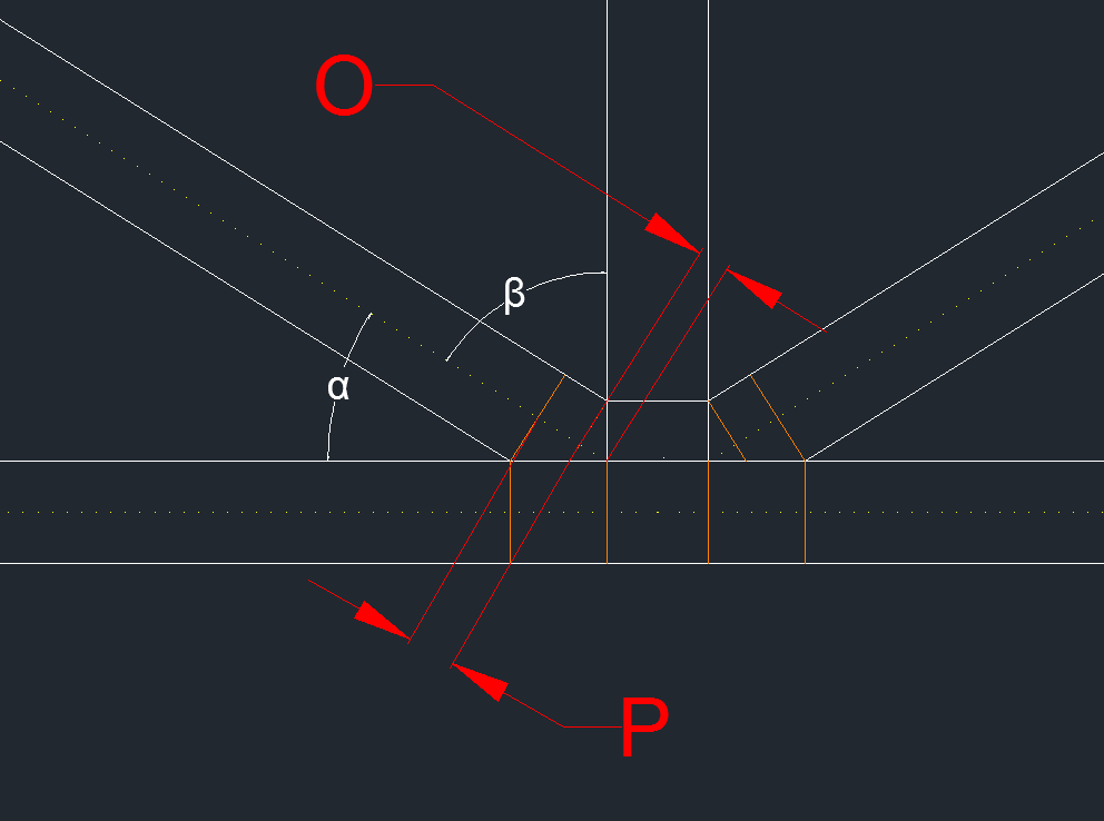
$ \alpha = \arcsin( \frac{I}{K}) $
$ \beta = \frac{\pi}{2} - \alpha $
$ O = \frac{W/2}{\tan(\beta)} $
$P =\frac {W/2}{\tan(\theta)}-O $
 |
| This is the final Roof Truss Design known as a Gable Truss Design |
 |
| These are some of the arbitrary labeled dimensions I came up with that would be useful in helping me make sure everything i |
 |
| Assuming length "L" was 10 ft, the width was 3.5 inches, and a slope of 30 degrees, these are the following calculated values |
 |
| This is the overall idea for the construction of the roof with reinforced wall support |
 |